Tuesday, April 28, 2020

What's the difference between a KG 13A and a KG 13B

Long time since my last post. I recently got asked what the difference between the KG 13A and KG 13B was. Externally, both were identical (with the exception of some smaller details like data plates and casting features depending on the manufacturer). The difference was the internal wiring only. Let's have a look at the wiring diagram that was glued to the inside of the wiring cover. First a KG 13A:

3) KG 13A WIRING DIAGRAM


2) KG 13B WIRING DIAGRAM


3) KG 13A WIRING DIAGRAM (Used in a Fw 190 instead of a KG 13B)

The only difference is an additional connection from 5 to the A-button in the KG 13B compared to the KG 13A. The third example above was installed in a Fw 190. Fw 190s were usually fitted with KG 13Bs, but in this example the internal wiring of a KG 13A was modified to reflect the diagram of a B. 

The Bf 109 usually had a KG 13A (or C in very late war production aircraft) and the Fw 190 usually a KG 13B (or C in very late war production aircraft). But there were exceptions and both aircraft types are known to have used both KG 13As and Bs.

I hope this clarifies some questions. If you have any control stick for identification, I'd like to hear from you. Please contact me (via this blog or via my website www.vintageeagle.com).


Wednesday, August 31, 2016

Original Heinkel He 111 Bomber Control Wheel (Steuerhorn) for Trade

UPDATE 2019: No longer available

I offer this control wheel in trade for a late war KG 12, KG 13 or KG 14 control stick in decent condition and with wartime markings. Please contact me if you are interested. The He 111 control wheel came from the estate of a former Wiener Neustädter Flugzeugwerke employee who worked in the Reparaturbetrieb near Vienna, Austria (see here for wartime photos: http://aviationhistorynorway.blogspot.ch/2013/01/daily-ebay-scan-wiener-neustadter.html)


Thursday, February 18, 2016

Control Stick of the Messerschmitt Bf 110 E/F/G


CONTROL STICK:
The Messerschmitt Bf 110 E/F/G subtypes used a KG 12E (Knüppelgriff 12E) control stick. It had the Fl-number Fl 47945 (Gerät-Nr. 102-56E). In the Bf 110 E/F subtypes the stick had the electrical wiring code P9 and in the Bf 110 G subtype the stick had the code V9 with P9 used instead for the Kampfdurchladeknopf (see below for more details about the Kampfdurchladung).

ARMAMENT:
The Bf 110F and Bf 110G existed with various armament configurations. Depending on the subtype of the Bf 110, there were typically either four 17mm MG 17 machine guns or two 30mm MK 108 canons in the upper nose section and either two 20mm MG FF/M or MG 151/20 in the lower nose section. Later subtypes also had two additional MG 151/20 installed in an optional pod underneath the fuselage. In addition, the Bf 110F/G could carry bombs on external ETC carriers.

BUTTONS:
A-Button:
The A-button, operated by the trigger on the top of the KG 12E control stick, fired the upper nose machine guns or canons.

B1-Button:
The B1-button at the top of the KG 12E fired the lower nose canons. If the Rüstsatz with two additional MG 151/20 canons under the fuselage was installed, the B1-button also fired the additional two MG 151/20 canons.

B2-Button:
The B2-button at the top left was used for releasing the external stores. Since the standard KG 12E did not have any B2-button, it was modified and a bracket added that held a button enclosed in a rubber piece. The modification was most likely done by Messerschmitt, but possibly by the stick manufacturer.

Kampfdurchladeknopf:
The four MG 17 had to be charged individually by pressing four buttons in the SKK 404/2 that was installed in the main instrument panel. Later, an additional button that was attached to the lower front of the control stick was installed. It was used to simultaneously charge the four MG 17, which was called Kampfdurchladung (KD) in the Bf 110 manuals. The Bf 110 manual L.Dv.T.2110 G-2 bis G-4/Wa (Stand Maerz 1943, Ausgabe April 1943) mentions that this button had previously been used for radio communication. However, if the additional button was indeed used for radio communications, it is unclear what the small button on the front of the KG 12E above the wiring terminal was used for in these cases since this was usually the button used for radio communications.

Auto Pilot Switch:
The Bf 110 G-4 was specifically built as a nightfighter and as such had an additional left/right switch LR I.3 built into the KG 12E about where the index finger of the pilot was. The pilot could operate the single axis auto pilot with this switch. Only very late in the war a dedicated control stick – called KG 13R – was introduced that had this switch already integrated at factory level. The majority of the others were modified earlier control stick types.


Electrical Wiring Diagram Bf 110F (KG 12E has code P9): 


 KG 12E control column in a Bf 110F (without KD button):


Electrical Wiring Diagram Bf 110G (KG 12E has code V9 and KD button P9):


Tuesday, January 26, 2016

WANTED

I am looking for the current owner of the KG 13B shown below. It was sold via eBay in 2011. I'd make a very interesting trade offer. I'd appreciate if you contact me if you are or know the current owner. Thanks!


Thursday, May 10, 2012

WANTED

Who knows who the current owner of the following German Messerschmitt control stick KG 13C is? I offer $40 if you can get me in touch with the current owner (proof that he is the current owner by more photographs of this stick on the latest newspaper). You can contact me by clicking on the banner "Wanted" on this blog at the right side:


Thursday, April 14, 2011

Focke Wulf Fw 190 G-3

CONTROL STICK:
The Focke Wulf Fw 190 G-3 used a KG 13B (Knüppelgriff 13B) control stick. It had the Fl-number Fl 47945 (Gerät-Nr. 102-288B).

ARMAMENT:
The Fw 190 G-3 was based in principle on the Fw 190 A-6, which was equipped with two fuselage mounted MG 17 7.92mm machine guns, two MG 151 20mm cannons in the wing roots and two wing mounted MG 151 20mm cannons. In the Fw 190 G-3, however, all except the two MG 151 cannons in the wing roots were usually not installed as the bomb load, and additional fuel carried in drop tanks underneath each wing made a weight reduction necessary.

Cockpit of Fw 190 G-3, W.Nr. 160016 (source: LIFE)
The photo on the left shows the cockpit of Fw 190 G-3, W.Nr. 160016, St.Kz. DN+FP, that was captured and later test flown in the USA. Several things are worth noticing. First, note that instead of a round counter and control box 4 (Schuss-, Zähl- und Kontrollkasten 4, SZKK 4) with 4 separate round counters, only two round counters are installed in a SZKK 2 for the two MG 151 in the wing roots at the top of the panel. Hence, the aircraft was indeed only equipped with two MG 151 cannons.

Many (if not all?) Fw 190 G-3 were equipped with a simple one-axis autopilot that allowed automatic rudder control which could be used to maintain a straight path in a dive when dive bombing. While on later aircraft equipped with singe-axis autopilots, the switch for the course correction was usually integrated into the top of the control stick, it was not in this Fw 190 G-3. Instead, the switch was moved into the auxiliary panel just above the ZSK 244 box. The autopilot could be turned on or off via a simple toggle switch and a rotating wheel allowed course corrections to the left or right. Interestingly, another type of course input instrument (so-called ‘Richtungsgeber’) also with an on/off switch can be seen in the photo at the bottom left. It is not clear which (or if both) of the two course input instruments were used together with the single-axis autopilot (and what the purpose of the other was).

Note also that the control stick is missing its data plate and features a metal stripe at the base of the stick that was fitted to hold the wires coming from the stick in place. This was a typical feature seen only on Fw 190 sticks.

ELECTRICAL WIRING DIAGRAM:
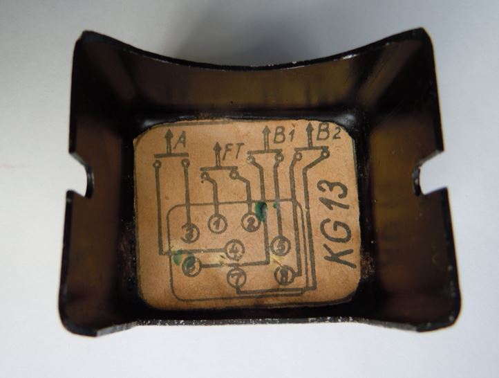
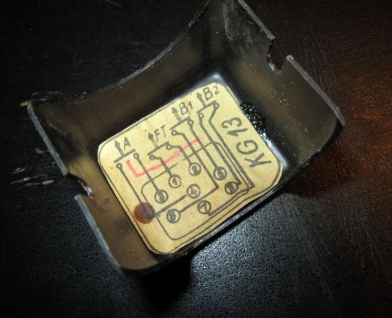
'V60' & MG 151 label on a Fw 190 KG 13B
The electrical wiring diagram code for the control stick was ‘V60’, which was not unique to the Fw 190 G-3, but to most Fw 190 subtypes.

BUTTONS:
A factory delivered KG 13B had three buttons used for weapons and one radio button. The top trigger was called A-Knopf (Knopf = button), the top center button was called B-Knopf (or also B1-Knopf) and the top left button was called B2-Knopf. Depending on the equipment the aircraft carried, additional buttons could be attached to the KG 13B control stick or the wiring was adjusted. The buttons in the Fw 190 G-3 were used as follows:

Fw 190 G-3 (two wing-root-mounted MG 151 cannons):
A-Knopf: 2x MG 151 (wing-root mounted), [only if installed: 2x MG 17 (fuselage mounted)]
B1-Knopf: [only if installed: 2x MG 151 cannons (wing mounted)]
B2-Knopf: drop ordnance

KG 13B of Fw 190 G-3, W.Nr. 160016 (source: LIFE)
Another photo showing the cockpit of Fw 190 G-3, W.Nr. 160016 (source: LIFE)

Tuesday, April 12, 2011

Messerschmitt Bf 109 G-6/U4

CONTROL STICK:
The Bf 109 G-6/U4 used a KG 13A (Knüppelgriff 13A) control stick. It had the Fl-number Fl 47915 (Gerät-Nr. 102-288A). 

Wiring diagram August '43
ARMAMENT:
The Bf 109 G-6/U4 was equipped with two fuselage mounted MG 131 13mm machine guns and one engine mounted MK 108 30mm cannon. Rüstsatz R6 offered the possibility to add one MG 151 20mm cannon underneath each wing.

ELECTRICAL WIRING DIAGRAM:
The electrical wiring diagram code for the control stick was the same as for the standard Bf 109 G-6 (click here to go to the Bf 109 G-6 article): ‘V23’.

Image from the Bf 109 G-6/U4 manual (August '43)
While the MG 131s were automatically charged when the safety switch in the round counter control box SZKK3 (Schuss-, Zähl- und Kontrol-Kasten 3) was toggled, the MK 108 cannon had to be manually charged. However, after take off the MK 108 was already charged and manually charging was only necessary in case of a gun jams. According to the wartime manual (dated August 1943) the MK 108 was charged via a small switch (see 'e' in image on the left and 'P301' in the image above) that was attached to the instrument panel. At the time the manual was prepared, it was envisaged to replace the switch by a button. The manual did not state where this button was to be located, but it was most likely attached directly to the control stick like seen on later Bf 109 G-10s.

BUTTONS:
A factory delivered KG 13A had three buttons used for weapons and one radio button. The top trigger was called A-Knopf (Knopf = button), the top center button was called B-Knopf (or also B1-Knopf) and the top left button was called B2-Knopf. Depending on the equipment the aircraft carried, additional buttons could be attached to the KG 13A control stick or the wiring was adjusted. The buttons in the Bf 109 G-6/U4 were used as follows:

Bf 109 G-6/U4 without Rüstsatz R6 (two wing-mounted MG 151 cannons):
A-Knopf: 2x MG 131 (fuselage mounted)
B1-Knopf: 1x MK 108 (engine mounted)
B2-Knopf: drop ordnance

When the Rüstsatz R6 was installed, it was originally planned to fire the MK 108 and MG 131s via the A-button and the wing mounted MG 151 cannons via the B1-button. However, a later added note in the manual stated that based on combat experience, the MK 108 should be fired via the B1-button and the wing mounted MG 151s together with the fuselage mounted MG 131s via the A-button:

Original scheme: Bf 109 G-6 with Rüstsatz R6 (two wing-mounted MG 151 cannons):
A-Knopf: 2x MG 131 (fuselage mounted) and 1x MK 108 (engine mounted)
B1-Knopf: 2x MG 151 (in wing pods)
B2-Knopf: drop ordnance

Revised scheme: Bf 109 G-6 with Rüstsatz R6 (two wing-mounted MG 151 cannons):
A-Knopf: 2x MG 131 (fuselage mounted) and 2x MG 151 (in wing pods)
B1-Knopf: 1x MK 108 (engine mounted)
B2-Knopf: drop ordnance

SOURCES:
L. Dv. T. 2109 G-6/U4/Wa. "Bf 109 G-6/U4. Schusswaffenanlage. Bedienungsvorschrift/Wa. (Stand Juli 1943) Ausgabe August 1943."